6381Y / BS 6004 PVC Copper Electrical Cable Multi Core For Apparatus Switch
APPLICATION
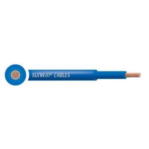
Flexible single core insulated and sheathed PVC cable. Suitable for DC power supplies on Telecoms equipment and power applications where flexibility is required.
CONSTRUCTION
Conductor
Class 5 flexible copper conductor to BS EN 60228 (previously BS 6360)
Insulation
PVC (Polyvinyl Chloride) Type TI1 according to BS 7655
Sheath
PVC (Polyvinyl Chloride) Type 6 according to BS 7655
CABLE STANDARDS
1.5mm2 to 35mm2: generally to BS 6004 50mm2 and above: BS EN/IEC 60502-1 BS EN/IEC 60332-1-2
The electrical and dimensional properties of this product are measured by the Technical and Quality Assurance department at the Sunwin Cables laboratory.
Cable performance in respect of conductor resistance, construction quality (workmanship),dimensional consistency, and other parameters are verified to published standardsand approved product drawings. Conformance to RoHS (Restriction of the use ofHazardous Substances) is determined and confirmed.
CHARACTERISTICS
Voltage Rating (Uo/U) 1.5mm2 to 35mm2: 450/750V 50mm2 and above: 600/1000V
Temperature Rating
Flexed: -15°C to +70°C
Minimum Bending Radius
Up to 50mm²: 3 x overall diameter Above 70mm²: 4 x overall diameter
Sheath Colour (Insulation Colour)
Blue (Blue) Grey (Grey) Green/Yellow (Green/Yellow) Special colours to order
DIMENSIONS
| Sunwin PART NO. |
NO. OF CORES |
NOMINAL CROSS SECTIONAL AREA
mm²
|
NOMINAL THICKNESS OF INSULATION
mm
|
NOMINAL THICKNESS OF SHEATH
mm
|
NOMINAL OVERALL DIAMETER
mm
|
NOMINAL WEIGHT
kg/km
|
| A1FY*0015 |
1 |
1.5 |
0.9 |
0.8 |
4.91 |
38 |
| A1FY*0025 |
1 |
2.5 |
0.9 |
0.8 |
5.35 |
49 |
| A1FY*004 |
1 |
4 |
1 |
0.9 |
6.25 |
71 |
| A1FY*006 |
1 |
6 |
1.1 |
0.9 |
7.6 |
101 |
| A1FY*010 |
1 |
10 |
1.2 |
1.1 |
8.56 |
152 |
| A1FY*016 |
1 |
16 |
1.2 |
1.1 |
9.75 |
215 |
| A1FY*025 |
1 |
25 |
1.4 |
1.1 |
11.5 |
307 |
| A1FY*035 |
1 |
35 |
1.4 |
1.1 |
12.5 |
405 |
| A1FY*050 |
1 |
50 |
1.4 |
1.4 |
15.1 |
580 |
| A1FY*070 |
1 |
70 |
1.4 |
1.4 |
16.95 |
769 |
| A1FY*095 |
1 |
95 |
1.6 |
1.5 |
19.1 |
1008 |
| A1FY*120 |
1 |
120 |
1.6 |
1.8 |
21.6 |
1282 |
| A1FY*150 |
1 |
150 |
1.8 |
1.8 |
23.4 |
1571 |
| A1FY*185 |
1 |
185 |
2 |
1.8 |
25.5 |
1895 |
| A1FY*240 |
1 |
240 |
2.2 |
1.8 |
28.5 |
2435 |
| A1FY*300 |
1 |
300 |
2.4 |
2.0 |
31.2 |
3050 |
| A1FY*400 |
1 |
400 |
2.6 |
2.1 |
35.3 |
4035 |
* Sunwin Part No. shown above designate the sheath colour and insulation colour (*). For each colour substitute * for a colour code as listed below.
e.g. A1FYBL/BL0015 = 1.5mm2 Blue (Blue)
Colour Codes
| COLOUR |
Blue (Blue) |
Grey (Grey) |
Green/Yellow (Green/Yellow) |
| CODE |
BL/BL |
GR/GR |
GY/GY |
CONDUCTORS
Class 5 Flexible Copper Conductors
|
NOMINAL CROSS SECTIONAL AREA
mm²
|
MAXIMUM DIAMETER OF WIRES IN CONDUCTOR
mm
|
MAXIMUM RESISTANCE OF CONDUCTOR AT 20ºC |
|
Plain Wires
ohms/km
|
| 1.5 |
0.26 |
13.3 |
| 2.5 |
0.26 |
7.98 |
| 4 |
0.31 |
4.95 |
| 6 |
0.31 |
3.3 |
| 10 |
0.41 |
1.91 |
| 16 |
0.41 |
1.21 |
| 25 |
0.41 |
0.78 |
| 35 |
0.41 |
0.554 |
| 50 |
0.41 |
0.386 |
| 70 |
0.51 |
0.272 |
| 95 |
0.51 |
0.206 |
| 120 |
0.51 |
0.161 |
| 150 |
0.51 |
0.129 |
The above table is in accordance with BS EN 60228 (previously BS 6360)
ELECTRICAL CHARACTERISTICS
Current Carrying Capacity
| NOMINAL CROSS |
REFERENCE METHOD A |
REFERENCE METHOD B |
REFERENCE METHOD C |
REFERENCE METHOD F |
|
SECTIONAL AREA
mm²
|
(ENCLOSED IN CONDUIT IN THERMALLY INSULATING WALL ETC) |
(ENCLOSED IN CONDUIT ON A WALL OR IN TRUNKING ETC) |
(CLIPPED DIRECT)
Amps
|
(IN FREE AIR OR ON A PERFORATED CABLE TRAY HORIZONTAL OR VERTICAL)
Amps
|
| |
Amps |
Amps |
|
|
|
Touching
|
Spaced by One Diameter |
| |
|
|
|
2 Cables Single-Phase AC or DC
or 3 Cables Three-Phase AC flat
|
| |
2 Cables |
3 or 4 Cables |
2 Cables |
3 or 4 Cables |
2 Cables |
3 or 4 Cables |
2 Cables |
3 Cables |
3 Cables |
|
|
| |
Single-Phase |
Three-Phase |
Single-Phase |
Three-Phase |
Single-Phase |
Three-Phase |
Single-Phase |
Three-Phase |
Three-Phase |
|
|
| |
AC or DC |
AC |
AC or DC |
AC |
AC or DC flat |
AC flat and |
AC or DC flat |
AC flat |
AC trefoil |
Horizontal |
Vertical |
| |
|
|
|
|
or touching |
touching or |
|
|
|
|
|
| |
|
|
|
|
|
trefoil |
|
|
|
|
|
| 1.5 |
14.5 |
13.5 |
17.5 |
15.5 |
20 |
18 |
- |
- |
- |
- |
- |
| 2.5 |
20 |
18 |
24 |
21 |
27 |
25 |
- |
- |
- |
- |
- |
| 4 |
26 |
24 |
32 |
28 |
37 |
33 |
- |
- |
- |
- |
- |
| 6 |
34 |
31 |
41 |
36 |
47 |
43 |
- |
- |
- |
- |
- |
| 10 |
46 |
42 |
57 |
50 |
65 |
59 |
- |
- |
- |
- |
- |
| 16 |
61 |
56 |
76 |
68 |
87 |
79 |
- |
- |
- |
- |
- |
| 25 |
80 |
73 |
101 |
89 |
114 |
104 |
131 |
114 |
110 |
146 |
130 |
| 35 |
99 |
89 |
125 |
110 |
141 |
129 |
162 |
143 |
137 |
181 |
162 |
| 50 |
119 |
108 |
151 |
134 |
182 |
167 |
196 |
174 |
167 |
219 |
197 |
| 70 |
151 |
136 |
192 |
171 |
234 |
214 |
251 |
225 |
216 |
281 |
254 |
| 95 |
182 |
164 |
232 |
207 |
284 |
261 |
304 |
275 |
264 |
341 |
311 |
| 120 |
210 |
188 |
269 |
239 |
330 |
303 |
352 |
321 |
308 |
396 |
362 |
| 150 |
240 |
216 |
300 |
262 |
381 |
349 |
406 |
372 |
356 |
456 |
419 |
| 185 |
273 |
245 |
341 |
296 |
436 |
400 |
463 |
427 |
409 |
521 |
480 |
| 240 |
321 |
286 |
400 |
346 |
515 |
472 |
546 |
507 |
485 |
615 |
569 |
| 300 |
367 |
328 |
458 |
394 |
594 |
545 |
629 |
587 |
561 |
709 |
659 |
| 400 |
- |
- |
546 |
467 |
694 |
634 |
754 |
689 |
656 |
852 |
795 |
Ambient temperature: 30ºC
Conductor operating temperature: 70ºC
The above table is in accordance with Table 4D1A of the 17th Edition of IEE Wiring Regulations.
Voltage Drop
|
NOMINAL CROSS SECTIONAL AREA
mm²
|
2 CABLES DC
mV/A/m
|
2 CABLES SINGLE-PHASE AC
mV/A/m
|
3 OR 4 CABLES THREE-PHASE AC
mV/A/m
|
|
Reference Methods A and B
(enclosed in conduit or trunking)
|
Reference Methods C and F (clipped direct, on tray or in free air) |
Reference Methods A and B
(enclosed in conduit
or trunking)
|
Reference Methods C and F (clipped direct, on tray or in free air) |
|
Cable Touching
|
Cable Spaced*
|
Cable Touching Trefoil |
Cable Touching Flat |
Cable Spaced* Flat |
| 1.5 |
29.0 |
29.0 |
29.0 |
29.0 |
25.0 |
25.0 |
25.0 |
25.0 |
| 2.5 |
18.0 |
18.0 |
18.0 |
18.0 |
15.0 |
15.0 |
15.0 |
15.0 |
| 4 |
11.0 |
11.0 |
11.0 |
11.0 |
9.5 |
9.5 |
9.5 |
9.5 |
| 6 |
7.3 |
7.3 |
7.3 |
7.3 |
6.4 |
6.4 |
6.4 |
6.4 |
| 10 |
4.4 |
4.4 |
4.4 |
4.4 |
3.8 |
3.8 |
3.8 |
3.8 |
| 16 |
2.8 |
2.8 |
2.8 |
2.8 |
2.4 |
2.4 |
2.4 |
2.4 |
| |
|
r |
x |
z |
r |
x |
z |
r |
x |
z |
r |
x |
z |
r |
x |
z |
r |
x |
z |
r |
x |
z |
| 25 |
1.75 |
1.80 |
0.33 |
1.80 |
1.75 |
0.20 |
1.75 |
1.75 |
0.29 |
1.80 |
1.50 |
0.29 |
1.55 |
1.50 |
0.175 |
1.50 |
1.50 |
0.25 |
1.55 |
1.50 |
0.32 |
1.55 |
| 35 |
1.25 |
1.30 |
0.31 |
1.30 |
1.25 |
0.195 |
1.25 |
1.25 |
0.28 |
1.30 |
1.10 |
0.27 |
1.10 |
1.10 |
0.17 |
1.10 |
1.10 |
0.24 |
1.10 |
1.10 |
0.32 |
1.15 |
| 50 |
0.93 |
0.95 |
0.30 |
1.00 |
0.93 |
0.19 |
0.95 |
0.93 |
0.28 |
0.97 |
0.81 |
0.26 |
0.85 |
0.80 |
0.17 |
0.82 |
0.80 |
0.24 |
0.84 |
0.80 |
0.32 |
0.86 |
| 70 |
0.63 |
0.65 |
0.29 |
0.72 |
0.63 |
0.185 |
0.66 |
0.63 |
0.27 |
0.69 |
0.56 |
0.25 |
0.61 |
0.55 |
0.165 |
0.57 |
0.55 |
0.24 |
0.60 |
0.55 |
0.31 |
0.63 |
| 95 |
0.46 |
0.49 |
0.28 |
0.56 |
0.47 |
0.18 |
0.50 |
0.47 |
0.27 |
0.54 |
0.42 |
0.24 |
0.48 |
0.41 |
0.16 |
0.43 |
0.41 |
0.23 |
0.47 |
0.40 |
0.31 |
0.51 |
| 120 |
0.36 |
0.39 |
0.27 |
0.47 |
0.37 |
0.175 |
0.41 |
0.37 |
0.26 |
0.45 |
0.33 |
0.23 |
0.41 |
0.32 |
0.155 |
0.36 |
0.32 |
0.23 |
0.40 |
0.32 |
0.30 |
0.44 |
| 150 |
0.29 |
0.31 |
0.27 |
0.41 |
0.30 |
0.175 |
0.34 |
0.29 |
0.26 |
0.39 |
0.27 |
0.23 |
0.36 |
0.26 |
0.15 |
0.30 |
0.26 |
0.23 |
0.34 |
0.26 |
0.30 |
0.40 |
| 185 |
0.23 |
0.25 |
0.27 |
0.37 |
0.24 |
0.17 |
0.29 |
0.24 |
0.26 |
0.35 |
0.22 |
0.23 |
0.32 |
0.21 |
0.145 |
0.26 |
0.21 |
0.22 |
0.31 |
0.21 |
0.30 |
0.36 |
| 240 |
0.18 |
0.195 |
0.26 |
0.33 |
0.185 |
0.165 |
0.25 |
0.185 |
0.25 |
0.31 |
0.17 |
0.23 |
0.29 |
0.16 |
0.145 |
0.22 |
0.16 |
0.22 |
0.27 |
0.16 |
0.29 |
0.34 |
| 300 |
0.145 |
0.16 |
0.26 |
0.31 |
0.15 |
0.165 |
0.22 |
0.15 |
0.25 |
0.29 |
0.14 |
0.23 |
0.27 |
0.13 |
0.14 |
0.19 |
0.13 |
0.22 |
0.25 |
0.13 |
0.29 |
0.32 |
| 400 |
0.105 |
0.13 |
0.26 |
0.29 |
0.12 |
0.16 |
0.20 |
0.115 |
0.25 |
0.27 |
0.12 |
0.22 |
0.25 |
0.105 |
0.14 |
0.175 |
0.105 |
0.21 |
0.24 |
0.10 |
0.29 |
0.31 |
Conductor operating temperature: 70ºC r = Resistive Component
x = Reactive Component z = Impedance Value
*Spacings larger than one cable diameter will result in a larger voltage drop.
The above table is in accordance with Table 4D1B of the 17th Edition of IEE Wiring Regulations.
For cables having conductors of 16mm2 or less cross-sectional area their inductances can be ignored and (mV/A/m)r values only are tabulated. For cables having conductors greater than 16mm2, cross-sectional area the impedance values are given as (mV/A/m)z, together with the resistive component (mV/A/m)r and the reactive component (mV/A/m)x.
The above paragraph is extracted from Appendix 4 of the 17th Edition of IEE Wiring Regulations.
The information contained within this datasheet is for guidance only and is subject to change without notice or liability. All the information is provided in good faith and is believed to be correct at the time of publication. When selecting cable accessories, please note that actual cable dimensions may vary due to manufacturing tolerances.